Optical Properties Monitor - Design
Optical Properties Monitor - Design
These pages contain information on the various aspects of the OPM’s design, including the mechanical and electrical design, the primary science instruments, and the environmental monitors. Also to be found here is a discussion of design constraints for the Mir mission.
Mechanical Design:
The OPM mechanicals were designed to make a lightweight, effective,
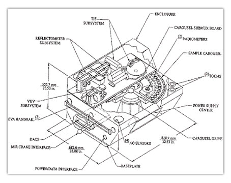
and mechanically uncomplicated payload which required no more resources than absolutely necessary. The OPM was designed to fit through all of the hatchways and tunnels in the Shuttle, SPACEHAB, and Mir, including the Shuttle docking adapter and the Mir’s airlock, plus all of the expected sizes of hatchways and tunnels aboard the ISS (according to the data that was available at the time of the design work). The OPM was constructed with a variety of mounting and hard points, and a versatile mounting base that allowed it to be mounted to a variety of different spacecraft exterior accommodations by way of a simple interface plate. The OPM had its own shipping rack; i a standard size double rack which was compatible with both Shuttle and ISS ISPR mountings. The OPM’s dimensions were:
- 82.87 cm in length (left to right, not including EVA handrails)
- 68.26 cm in depth (at the longest measurement)
- 52.07 cm in height (to tallest point, at top of instrument enclosure)
- Mass: 115 kg
Placement and layout of the various OPM components was chosen for maximum science return while maintaining mechanical simplicity. The samples were mounted on a rotating carousel, which rotates to first expose the samples and then bring them into the corresponding instruments for measurement. Half of the carousel’s service contained samples; the other half was blank. The placement of the instruments in an enclosure which overhangs half of the carousel allowed for easy alignment of the samples for measurement, and the enclosure created a protected stowage area for the samples when the OPM was not operating (the carousel simply rotated so that the blank half is exposed). The instrument arrangement also allowed for placement of some parts of the Vacuum Ultraviolet (VUV) instrument underneath the samples, which was necessary due to the nature of the instrument. This arrangement of the instruments slightly limited the experiment’s exposure view angle, but placement for a total 180-degree view by the samples would have required a much more complex mechanical transport to move the samples inside the OPM’s body for measurements. The body itself contained the OPM’s power supplies, the carousel drive, and the DACS electronics.
The carousel was driven by a stepper motor, which could position the carousel to within an angular position accuracy of 5.4 arc minutes (0.084 degrees, or .0015 radians). A rotation of 180 degrees (½ turn) took approximately 1 minute, 5 seconds, at the drive’s maximum rate. The carousel contained a number of sensors (radiometers and calorimeters) on the rotating portion. These were electrically connected by way of a flexible cable; no slip rings or commutators were used. The carousel did not have a hard stop; the flexible cable allowed for a rotation range of slightly less than 1-1/2 turn, which was enforced by the software. One special feature of the carousel was a calibration sample for the Total Integrated Scatter (TIS) instrument; this was mounted on the blank half of the carousel and had a trap door which covered the sample. The door opened only when the sample was inside the TIS instrument.
The OPM was designed for flight aboard a manned spacecraft, and the design accomplished maximum efficiency in a complete package while posing minimal burdens on the flight crew, and avoiding hazards to the crew. The requirements for flight aboard a manned spacecraft, which OPM met, can be summarized as:
- Minimize size and mass.
- Be capable of surviving Shuttle launch and landing shocks and vibrations under anticipated nominal and off-nominal conditions.
- Physical compatibility with Shuttle, Mir, and SPACEHAB interfaces and accommodations, such as hatchways and payload racks.
- Minimize use of spacecraft resources and crew labor.
- Avoid posing hazards to the spacecraft and crew.
Most of the OPM’s structure was composed of 6061-T6 Aluminum, which was selected for surviving extended exposure to the space environment. For thermal control, the OPM made extensive use of advanced thermal control coatings; this allowed the OPM to operate outside the spacecraft, in the space environment, and maintain reasonable internal and touch temperatures without requiring a cold plate. The instrument cover enclosure served as a controlled radiative surface for dissipating instrument heat during measurement sequences without reaching an excessive temperature, and without creating a heat sink during the OPM’s low-power passive exposure periods. The mounting base and interface plate mechanism was also designed to minimize heat transfer between the OPM and the spacecraft to which it was mounted. Extensive thermal analysis was performed to verify these properties.The OPM contained a number of design features to facilitate handling during EVA. The two EVA handrails were gold anodized for easy recognition by the crew, and met the NASA and RSA requirements for reach and accessibility by the gloved hand, as well as touch temperature constraints. The handrails were hard points and, when the OPM was mounted, could be used as tether points by the crew. The sample cover was anchored with EVA-qualified pip pins, and its handle could be used as a third handle for the OPM itself when the cover was in place (although the sample cover handle could not be used as a tether point). The OPM also had a fixture for attachment to the Mir crane, and this fixture could be changed to accommodate other transport mechanisms (such as the Space Station Remote Manipulator System) as needed. The electrical connectors were twist-to-lock types which were designed for use with the gloved hand, and the OPM’s base plate contained attachment points for tie down of the electrical cable while the OPM was being translated to and from its operating location. The base plate also contained a stowage for the sample cover. Stowage or restraint was provided for all electrical connector caps and covers, so that there were no components dangling when the OPM was in place.
In flight and in operation, the OPM was designed to present no hazards to the spacecraft crew. In order to avoid even the remote possibility that a spilling or broken sample might pose any hazard to the flight crew, the OPM employed four layers of protection:
- The carousel is rotated to the samples-stowed position at any time when the experiment is accessible to the crew. In this position, all of the material samples are concealed underneath the instrument area, the cover of which fits very closely to the top surface of the carousel.
- A plastic cover is taped to the exposed half of the carousel, which completely seals the carousel and interior areas of the OPM. This is removed prior to deployment.
- A sample cover plate is placed over the carousel area and, together with the instrument enclosure, completely covers the sample carousel and all of the sensors and instruments. This sample cover is removed as the final step in the deployment EVA, and replaced as the first step in the retrieval EVA. (The sample cover also protects the environmental sensors mounted on the carousel deck from damage.)
- The entire OPM payload is wrapped in a heavy beta cloth protective cover when stowed inside the spacecraft.
One other safety consideration is the use of the lasers in the Total Integrated Scatter (TIS) instrument. To avoid presenting a vision hazard, the TIS was designed so that with the instrument enclosure cover in place, all laser light is “trapped” and there is no possibility of any scatter or reflection of the beam reaching a crew member’s eyes.
Electrical Design:
The OPM’s electricals consisted mainly of a power supply, active thermal control system, and the DACS computer. The power supply converted the 28V DC power from the spacecraft to the various voltages needed by the OPM electronics.
The active thermal control system consisted of two 50-watt case heaters, under the control of the DACS. Each heater had its own temperature sensor and operated independently.
The DACS is the brains of the OPM. Adapted from a commercial off-the-shelf spacecraft processor system from Southwest Research, it consisted of two printed-circuit boards: a processor board and an I/O interface board. The processor board contained a space-hardened version of the commercial 80186 processor which has also been the basis for many personal computers. The processor board was equipped with 512 kilobytes of random access memory (RAM), and 6 megabytes EEPROM to store the OPM control software and for archival memory for the data collected by the OPM. All program and data information was stored in this memory; the OPM did not contain any mass storage device such as a disk drive.
OPM Software:
In operation, the DACS controled the OPM instruments, collected and stored data, and communicated with the Mir MIPS laptop via its RS-422 interfaces. The software initiated the measurement sequences, controled the operation of each instrument and the carousel, and stored the data collected in the EEPROM. Data from the environmental monitoring instruments was collected continuously between measurement sequences, and stored in the EEPROM along with the measurement data.
Pre-loaded on the MIPS laptop was software which enabled it to communicate with the OPM through the laptop’s RS-232 port. This software used a modified version of the common X-Modem protocol to retrieve data from the OPM and send commands to it. The normal procedure, executed once a week by an astronaut, transfered all of the data collected since the last data transfer. The data was transferred directly from the EEPROM to the laptop. The OPM software kept track of which data had already been collected, and only transfered new data. (previously transferred data could be re-retrieved via a special procedure if need be.) As a backup data source, the OPM retained collected data in the EEPROM as long as possible; its capacity (as designed) was sufficient to retain all of the data for a mission of up to 20 months.
Special procedures could be executed on the laptop to alter OPM operational parameters. Many aspects of the OPM’s operation could be changed, including the scheduling of the measurements and operational parameters of the individual instruments. The OPM software also contained an end-of-mission deactivation procedure that stowed the samples and prepares the payload for retrieval.
Instruments Design:
Space environment effects on the OPM samples were measured using three instruments: a Vacuum Ultraviolet spectrometer (VUV), a spectro-reflectometer, and a total integrated scatterometer. Each row of samples on the carousel corresponded to one of these instruments. The outer row was the VUV experiment, the next row was the solar absorption and emittance study, and the third row was the scatter experiment. The innermost row of samples on the carousel consisted of passive samples which were not measured in flight.
The Vacuum Ultraviolet spectrometer (VUV) measured the ability of materials samples to reflect and transmit light in the near- to middle-ultraviolet portion of the electromagnetic spectrum (approximately 1216-2500 Å wavelength range). A special arc-discharge lamp, known as a deuterium lamp (similar in principle to a mercury vapor streetlight) produced the ultraviolet light, and a set of filters selected the specific wavelength to be measured. The transmittance and reflectance data from the VUV helped to fill a general void of optical properties data for materials used in the UV range (MgF, LiF, CaF, etc.). The data is useful to experiment designers which must expose these materials to the space environment.
The spectro-reflectometer is an instrument that measures the reflectance of materials samples at wavelengths ranging from the middle-infrared, through the near infrared and visible light wavelengths, to the near ultraviolet. The range of wavelengths measured are in the range of 250-2500 nm. (Visible light spans approximately 400 to 800 nm.) To cover this large range, the reflectometer used two light sources: a tungsten halogen lamp (similar to the halogen lamps used in some residential light fixtures) and a deuterium lamp are combined; the deuterium lamp served the ultraviolet and visible blue and violet portion while the tungsten lamp covered the remainder of the visible light and all of the infrared portion. The reflectometer measured the total hemispheric reflectance, i.e., all of the radiation reflected in any direction by the sample being measured; it did this using an integrating sphere which captured all of the reflected energy. The wavelength to be measured was selected using a mechanism known as a prism monochromater which splits the light source using a prism, and then employs a moving mirror in front of a slit to screen out all but the desired wavelength. Many surfaces can be tested for degradation by the spectro-reflectometer, including heat-reflecting paints and coatings intended for use both on the ISS and for commercial use.
The Total Integrated Scatter (TIS) instrument measured how much light is scattered (in other words, reflected away at an angle other than the angle of direct reflection). It performed this measurement at two specific wavelengths, 532 nm (visible green) and 1064 nm (near infrared), using a pair of lasers as the light sources. The scattered light was collected for measurement by way of a Coblentz sphere, which is a hemispherical mirror. The TIS scatter measurement is an indication of how rough the surface of a material is, which in turn indicates to what extent the material’s surface has been damaged by the space environment. Smooth mirrored surfaces, such as those used in solar collectors and radiators, and heat-resistant coatings are measured by this instrument. Also measured and of particular interest are plastics which are intended to be used as overcoatings and electrical insulators. One such material is Kapton, widely used in spacecraft but known to be damaged by atomic oxygen (AO) in low Earth orbit; some of the TIS samples consisted of AO-resistant materials which have been developed as substitutes for Kapton for possible use on the ISS.
Design Constraints:
The OPM was originally designed to fly on the European Space Agency’s EURECA satellite. The EURECA was an unmanned, free-flying payload that was launched in the Space Shuttle, released to fly free for a one-year mission, and then returned to Earth by another Shuttle to be refurbished and launched again. However, the EURECA program was cancelled in 1994 after one flight, and it became necessary to find another spacecraft on which to fly the OPM.
At this time, an opportunity arose to fly as part of NASA’s International Space Station Phase I program. This was a joint American-Russian program to, among other things, fly U.S. payloads aboard the Russian Mir space station in order to gain experience for subsequent operations aboard ISS. Among its advantages were very long duration, a stable platform, and crew presence to fix problems if necessary. However, some changes were necessary to the OPM design in order to fly aboard Mir, and some additional steps had to be taken to qualify to fly the OPM on Mir.
The most significant impact on the design of the OPM were the Mir hatch and passageway constraints. As originally planned for the EURECA mission, the OPM would be pre-integrated with the EURECA satellite prior to the mission, and since the EURECA would be loaded directly into the Shuttle’s payload bay, it would not ever be necessary to pass the OPM through any spacecraft interior. After the switch it became apparent that the OPM would have to be deployed through either the Mir or the Shuttle airlocks, which meant the payload had to pass through tunnels and hatchways in the interior of the respective spacecraft. Originally, the main (lower) portion of the OPM’s case had been designed as a simple rectangle. However, in order to pass through a circular hatchway, the lower front panel was beveled inwards; this reduced the diameter required for passage. Another change was in the method of mounting the payload to the spacecraft; in the original plan, the OPM would have been integrated with the EURECA before flight, so there was no reason to provide any in-flight attach and detach capability. However, on Mir, installation would be done by astronauts/cosmonauts during an extravehicular activity (EVA), and they had to be able to mount and dismount the OPM while in EVA gloves and suits and lacking any leverage. In addition, the mounting means itself was different; on EURECA the OPM would have been attached to a satellite truss, while the Mir used a ball-and-socket mechanism. An interface plate was fabricated which adapted the OPM to a device called variously the “Mir interface adaptor” or the “solar array latch” (the mounting site had originally been used to transport a solar array), supplied by RSC Energia. The interface adaptor had a three-position handle which the EVA crew members used to lock and unlock the interface adaptor from the mounting base on the Mir docking module, and this constituted the complete mechanical attachment between the OPM and Mir.
It was also necessary to provide for handling of the OPM by EVA astronauts. Towards this end two large handles were added, one at each end of the case; these handrails were sized and qualified to be handled by EVA astronauts, allowing for factors such as the limited grip ability of the gloves (it is difficult to close one’s hand in a pressure suit because the pressure tends to hold the glove fingers straight) and the clearance required between the handle and the side of the case in order for the gloved fingers to fit in the space. The electrical cable connector was changed to one capable of being connected and disconnected in the EVA operation. In addition, a ball fixture was added to the right side for capture by the Mir cargo crane, so that the OPM could be moved that way rather than by hand, saving significant amounts of time during the EVA.
Finally, changes were necessary to allow for the differences in EURECA’s and Mir’s data interfaces and downlink capability. EURECA provided a near-continuous, real-time data downlink via the TDRSS satellite system and was operated mainly from the ground except during the deploy and retrieval. However, Mir at the time of the OPM mission did not have a real-time downlink capability available for payload use; rather, downlink was performed using a file transfer process executed by a crew member. The OPM’s data I/O software modules were changed to conform to this interface. In addition, a small software module was needed on the computer (a laptop) to which the data was transferred, and this was written; in the process, the OPM engineers took the opportunity to provide additional user interface capabilities on the laptop so that the crew could send commands to the OPM and execute off-nominal procedures if need be. The electrical/data cable was changed to a design using two parts. Part of the cable was outside of the spacecraft and part was inside; the two halves met at a bulkhead connector which was already built in to the side of the docking module. The interior cable connected to a power outlet to provide power to the OPM, and provided primary and backup data ports for the laptop. In addition, a pair of signal lights were added to the cable to give the crew a visual indication of the OPM’s general operating state without having to connect the laptop. Data retrieval and transfer to the ground were executed once per week.